Описание
 | ||
 |  |  |
 |  | 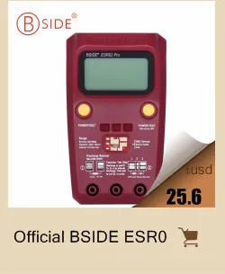 |
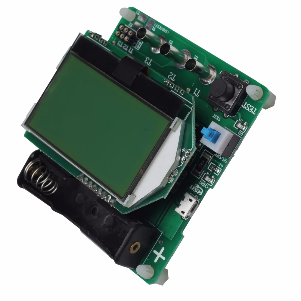
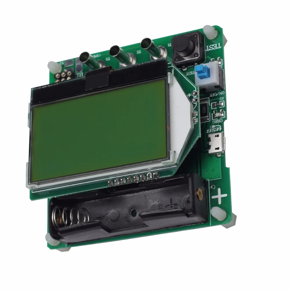
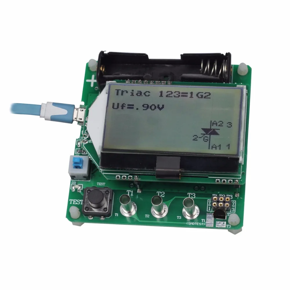
Transistor Tester Diode Triode inductor Capacitance resistor MOS/PNP/NPN ESR02 Digital LCR Meter Multimeter
Attention:
1. Always be sure to discharge capacitors before connecting them to the Tester! The Tester may be damaged before you have switched it on. There is only a little protection at the CPU ports. Extra caution is required if you try to test components mounted in a circuit. In either case the equipment should be disconnected from power source and you should be sure, that no residual voltage remains in the equipment.
2. USB socket is used to charge the battery and to power the system voltage can’t be higher than 5.5V
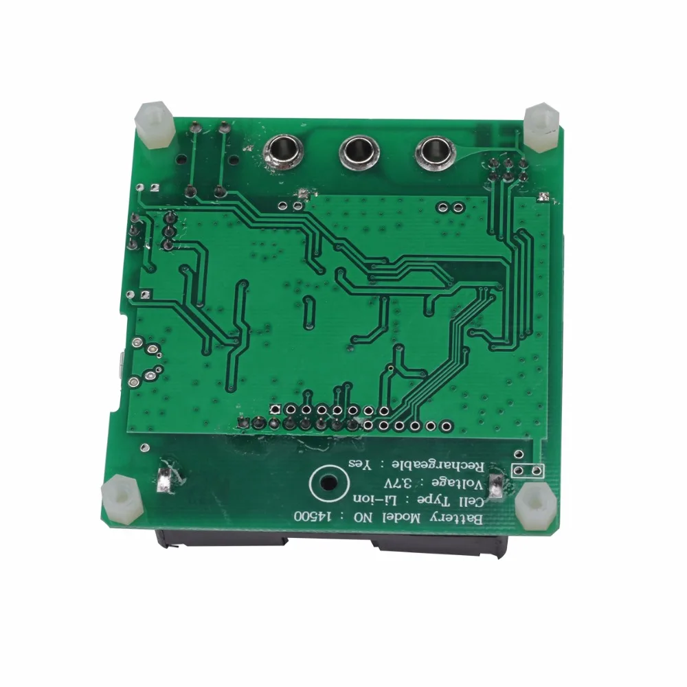
3. System uses a 3.7V lithium-ion rechargeable batteries, do not use any other type of battery! In order to avoid damage!
Features:
1. Displaying the results to a 128*64 Graphic LCD-Display.
2. One key operation with automatic power shutdown.
3. Automatic detection of NPN and PNP bipolar transistors, N- and P-Channel MOSFETs, JFETs, diodes, double diodes, Thyristors and Triacs.
4. Automatic detection of pin layout of the detected part.
5. Measuring of current amplification factor and Base-Emitter threshold voltage of bipolar transistors.
6. Darlington transistors can be identified by the threshold voltage and high current amplification factor.
7. Detection of the protection diode of bipolar transistors and MOSFETs.
8. Measuring of the Gate threshold voltage and Gate capacity value of MOSFETs.
9. Up to two Resistors are measured and shown with symbols and values with up to four decimal digits in the right dimension. All symbols are surrounded by the probe numbers of the Tester (1-3). So Potentiometer can also be measured. If the Potentiometer is adjusted to one of its ends, the Tester cannot differentiate the middle pin and the end pin.
10. Resolution of resistor measurement is now up to 0.01, values up to 50M are detected.
11. One capacitor can be detected and measured. It is shown with symbols and value with up to four decimal digits in the right dimension. The value can be from 25pFto 100mF. The resolution can be up to 1pF.
12. For capacitors with a capacity value above 0.18uF the Equivalent Serial Resistance (ESR) is measured with a resolution of 0.01 and is shown with two significant decimal digits.
13. Up to two diodes are shown with symbols or symbols in correct order. Additionally the flux voltages are shown.
14. LED is detected as an diode, the flux voltage is much higher than normal. Two-in-one LEDs are also detected as two diodes.
15. Zener Diodes can be detected, if reverse break down Voltage is below 4.5V. These are shown as two diodes, you can identify this part only by the voltages. The outer probe numbers, which surround the diode symbols, are identical in this case. You can identify the real Anode of the diode only by the one with break down (threshold) Voltage nearby 700mV!
16. If more than 3 diodes type parts are detected, the number of founded diodes is shown additionally to the fail message. This can only happen, if Diodes are attached to all three probes and at least one is a Z-Diode. In this case you should only connect two probes and start measurement again, one after the other.
17. Measurement of the capacity value of a single diode in reverse direction. Bipolar Transistors can also be analysed, if you connect the Base and only one of Collector or Emitter.
18. Capacitors with value below 25pF are usually not detected, but can be measured together with a parallel diode or a parallel capacitor with at least 25pF. In this case you must subtract the capacity value of the parallel connected part.
19. For resistors below 2100 also the measurement of inductance will be done. The range will be from about 0.01mH to more than 20H, but the accuracy is not good. The measurement result is only shown with a single component connected.
20. Testing time is about two seconds, only capacity or inductance measurement can cause longer period.
21. All the DUT can be electrically symbols displayed on the LCD, not repeat them here
The measurement operation:
Using of the Transistor-Tester is simple.
Anyway some hints are required.
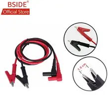
In most cases are wires with alligator clips connected to the test ports with plugs.
Also sockets for transistors can be connected.
In either case you can connect parts with three pins to the three test ports in any order.
If your part has only two pins, you can connect these pins to any two of the tree test ports.
Normally the polarity of part are irrelevant, you can also connect pins of electrolytic capacitors in any order.
The measurement of capacity is normally done in a way that the minus pole is at the test port with the lower number.
But, because the measurement voltage is only between 0.3 V and at most 1.3V, the polarity does not matter.
When the part is connected, you should not touch it during the measurement.
You should put it down to a non-conductive pad if it is not placed in a socket.
You should also not touch to the isolation of wires connected with the test ports.
Otherwise the measurement results can be affected.
Then you should press the start button.
After displaying a start message, the measurement result should appear after two seconds.
If capacitors are measured, the time to result can be longer corresponding to the capacity.
Pacakge:
1 x ESR02 meter;
1 x pair alligator test lead;
Характеристики
- Бренд
- BSIDE
- Индивидуальное изготовление
- Да
- Номер модели
- ESR02
Сопутствующие товары